This page last updated on Friday, October 13, 2006 at 9:45:58 AM
| Home | | ATV | | ATV Centre | | Schools | | Fenton Relay | | Antenna Theory | | Other Pages |
Practical Examples of Aerial Design
|
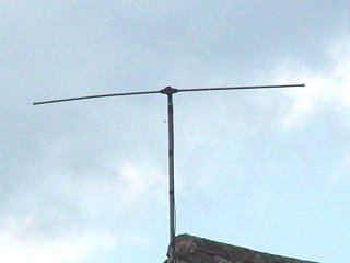
This is the simplest type of antenna, a half wave dipole. There are no directors and a reflector - it is a bi-directional VHF radio aerial, with its gain lobes coming towards the camera and away. |
|
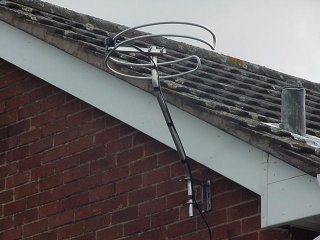
This relatively modern design utilises a dipole that has been bent into a circle to maximise its directional capabilities. I imagine the dipole's been folded because bending it into a circle alters it impedance, and folding corrects it. |
|
|
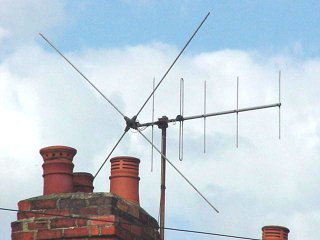
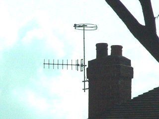
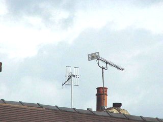
You don't see many of these around any more! This is a VHF TV aerial for 405-line transmissions. This picture was taken in 2000, 15 years after VHF TV transmissions ceased in the UK. Notice that the director separation changes as you move down the boom - this is to increase the bandwidth of the aerial. Tony Currie: "The part to the right (Dipole + directors) is for Band III. The part to the left (the X) is the Band I aerial which is a dipole with reflector at 90 degrees. "These pairs were very common in the late 50s and throughout the 60s. In the earler 50s it was more common to use an H aerial for Band 1 - a straight dipole + reflector. Many aerial manufacturers produced aerials which physically combined the Band I and Band III elements together. The output of each aerial was then fed into a combiner (often just taped to the mast) and thence to a single piece of coax." If you look closely you can see two pieces of coax, one from the 'X' and one from the folded dipole. |
|
The large aerial here is a VHF radio antenna. It has an unfolded dipole and a reflector. A vertically polarised UHF TV aerial is underneath. |

|
|
Here's a circular folded dipole VHF radio aerial, and underneath a UHF TV antenna. All of the vertically polarised (ie the antenna elements are vertical) UHF aerials on this page are group A aerials, which have a bandwidth which covers channels 21-34. If you look closely you can see that the directors are gradually becoming shorter as they get further from the dipole. This is to increase the bandwidth. The reflector is of the plate type. |
|
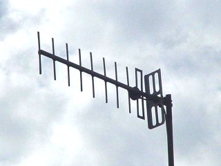
Here's a close-up of a vertically polarised UHF TV aerial. It has a plate-type reflector, tubular directors and a plate-type folded dipole. The blob attached to the dipole is a plastic weatherproof box which contains the connections between the aerial and the feeder cable. Signal strength is greatly reduced if water gets into the co-ax. |
|
|
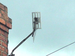
Here's a back view of a UHF TV aerial. Here you can see the clamp used to hold the antenna onto its mounting. The feeder cable is taped to the mounting. |
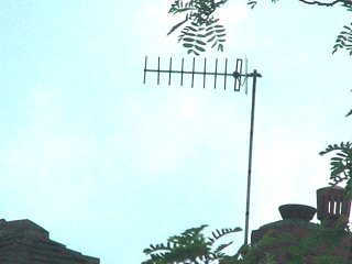
| In this weather-beaten example you can see how the directors become shorter the further away the get from the dipole. |
|
|
Here's a shiny new vertically polarised UHF TV aerial (with an unusually designed reflector) and a horizontally polarised high-gain UHF TV aerial with 18 elements as opposed to the usual 10 or 12 in strong signal areas. The low-gain antenna is receiving pictures from the Fenton relay whilst the high-gain one is pointing towards the Sutton Coldfield main station. |
|
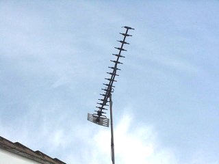
This hapless creature spent an evening bashing against the side of my parents' house during a storm. I believe it's a wideband model (i.e. covers all UHF channels from 21-68) as the separation between the directors changes markedly from one end of the boom to the other. Which means that we we ripped off, as it should have been a group C/D aerial for receiving pictures from Winter Hill. |
|
|
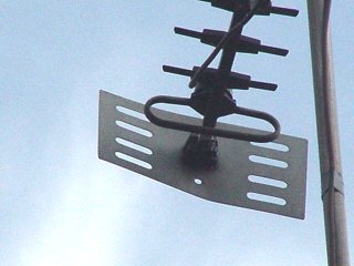
Here's a close-up of the folded dipole and rather crumpled reflector. |
|
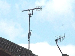
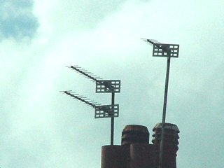
Here's and 18-element horizontally-polarised aerial (also pointing towards Winter Hill) and a low-gain vertically polarised antenna, both with unusual reflectors. This type of reflector design appears to have been popular in the 1970s. |
|
|
Here's some medium gain aerials, probably 14 element, pointing towards Sutton Coldfield. |
|
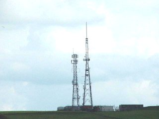
For one last picture, here's the Fenton relay in Stoke-on-Trent, where all of the vertically polarised aerials on this page were pointing towards. Click here for more on the Fenton relay. |

